
 Español
 Portugues
 简体中文
简体中文 Pусский


1.the basic principle of antenna
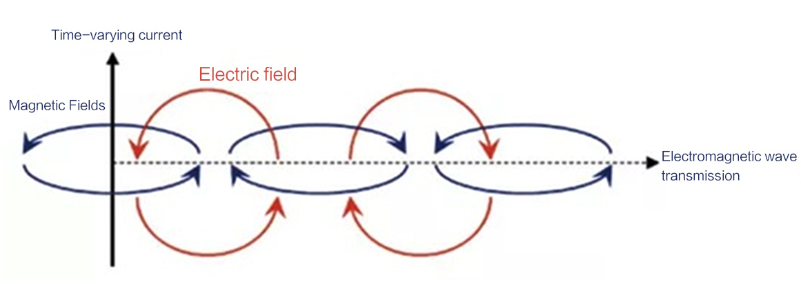
The basic principle of the antenna is the high-frequency current around it to produce a change in the electric and magnetic fields, according to Maxwell's electromagnetic field theory, "the change in the electric field produces a magnetic field, the change in the magnetic field produces an electric field", so that the continuous excitation, the realization of the wireless signal propagation.
2.the main parameters of the antenna and the concept
1) Gain
Antenna is a passive device, here the gain refers to the antenna in a radiation direction of the antenna radiation direction map strength and the reference antenna strength ratio, generally expressed in logarithmic. If the reference antenna is omnidirectional antenna, the unit is dBi, dipole antenna gain is 2.14dBi. due to the ideal omnidirectional antenna can not be achieved (dipole antenna H surface directionality for a circle), dipole antenna (half wavelength, single oscillator length of 1/4 wavelength) is also commonly used to do reference antenna, when the gain unit is dBd.
Antenna gain is used to measure the ability of the antenna to send and receive signals in a particular direction, it is one of the important parameters to choose the antenna.
2) Directional map
Radiation direction map is the antenna transmitting or receiving field strength graphical description, is a three-dimensional map of the gain. As the antenna to three-dimensional space radiation, need several graphics to describe. General antenna radiation relative to an axis symmetry (such as dipole antenna, spiral antenna and some parabolic antenna), usually only consider the radiation direction map of the horizontal and vertical two-dimensional cross-section, then only a direction map.
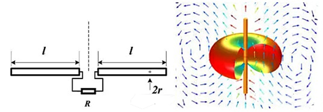
The above figure on the left for the conventional dipole antenna, the center feed, after simulation (right) can be seen: from the top of the antenna to see the radiation field is circular, the energy to the direction of radiation perpendicular to the antenna axis, using a directional map expressed as follows.

3) Beam width/flap
In the power direction diagram, the maximum power radiation direction corresponding to become the main lobe, the relative maximum radiation direction power down to half or less than the maximum 3dB beam width angle between the two points is called half power lobe width. Similarly, 6dB beamwidth and 12dB beamwidth can be defined as needed.
The higher the gain of the antenna, the better the directionality, the more concentrated the energy, the narrower the flap. High gain antenna radiation direction map is often accompanied by "side lobe" (side lobe) and back lobe (back lobe). Side lobe is the gain in addition to the main lobe (the highest gain "beam") outside the beam. Side lobe in such as radar and other systems need to determine the direction of the signal, will affect the quality of the antenna, due to power distribution side lobe also make the main flap gain is reduced.

4)Multi-beam
The above antenna direction diagram only one main beam, multi-beam use multiple antennas to form a different beam pointing (radar applications) or cover a wider range (communication applications), generally through the phase shifter to adjust the phase of each antenna to achieve.


5) the antenna polarization (Polarization)
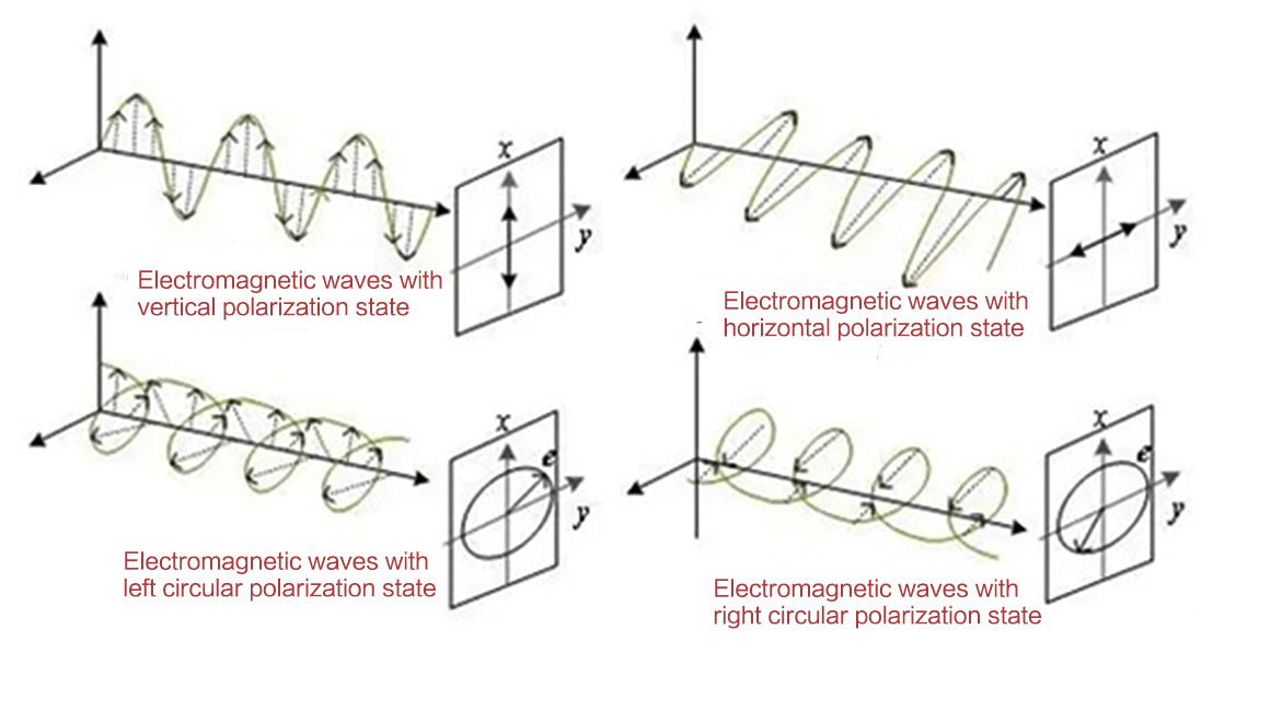
Polarization is a different way of electromagnetic wave transmission: generally have line polarization (horizontal, vertical) and circular polarization (left rotation, right rotation), elliptical polarization, etc..
Most radar systems are unipolarized. This is because the transmitter and receiver are working on the same antenna, so whatever the polarization is, it will come back strongly. The polarization that is the same as the transmitted polarization is called "co-polarization" and the opposite polarization is called "cross-polarization".
A line polarized electromagnetic wave can be decomposed into two orthogonal waves by a 90° polarizer, so that the synthesized transmission vector rotates along the transmission axis into a circularly polarized transmission, with left or right rotation depending on whether the phase shift of the two orthogonal waves is +90° or -90°.
In general, the antenna polarization can be chosen according to the application requirements. Different applications can get better results from different polarization methods. For example, vertically polarized antennas perform better in terrestrial mobile communications applications because vertically polarized electromagnetic waves pass through undulating terrain more easily than horizontally polarized waves, while horizontally polarized approaches perform better in ionosphere-dependent and often long-range communications applications. In addition, circular polarization is commonly used for satellite communications because it generally better mitigates the fading caused by satellite directional shift.
The basic principle of the antenna is the high-frequency current around it to produce a change in the electric and magnetic fields, according to Maxwell's electromagnetic field theory, "the change in the electric field produces a magnetic field, the change in the magnetic field produces an electric field", so that the continuous excitation, the realization of the wireless signal propagation.
2.the main parameters of the antenna and the concept
1) Gain
Antenna is a passive device, here the gain refers to the antenna in a radiation direction of the antenna radiation direction map strength and the reference antenna strength ratio, generally expressed in logarithmic. If the reference antenna is omnidirectional antenna, the unit is dBi, dipole antenna gain is 2.14dBi. due to the ideal omnidirectional antenna can not be achieved (dipole antenna H surface directionality for a circle), dipole antenna (half wavelength, single oscillator length of 1/4 wavelength) is also commonly used to do reference antenna, when the gain unit is dBd.
Antenna gain is used to measure the ability of the antenna to send and receive signals in a particular direction, it is one of the important parameters to choose the antenna.
2) Directional map
Radiation direction map is the antenna transmitting or receiving field strength graphical description, is a three-dimensional map of the gain. As the antenna to three-dimensional space radiation, need several graphics to describe. General antenna radiation relative to an axis symmetry (such as dipole antenna, spiral antenna and some parabolic antenna), usually only consider the radiation direction map of the horizontal and vertical two-dimensional cross-section, then only a direction map.
The above figure on the left for the conventional dipole antenna, the center feed, after simulation (right) can be seen: from the top of the antenna to see the radiation field is circular, the energy to the direction of radiation perpendicular to the antenna axis, using a directional map expressed as follows.
3) Beam width/flap
In the power direction diagram, the maximum power radiation direction corresponding to become the main lobe, the relative maximum radiation direction power down to half or less than the maximum 3dB beam width angle between the two points is called half power lobe width. Similarly, 6dB beamwidth and 12dB beamwidth can be defined as needed.
The higher the gain of the antenna, the better the directionality, the more concentrated the energy, the narrower the flap. High gain antenna radiation direction map is often accompanied by "side lobe" (side lobe) and back lobe (back lobe). Side lobe is the gain in addition to the main lobe (the highest gain "beam") outside the beam. Side lobe in such as radar and other systems need to determine the direction of the signal, will affect the quality of the antenna, due to power distribution side lobe also make the main flap gain is reduced.
4)Multi-beam
The above antenna direction diagram only one main beam, multi-beam use multiple antennas to form a different beam pointing (radar applications) or cover a wider range (communication applications), generally through the phase shifter to adjust the phase of each antenna to achieve.
5) the antenna polarization (Polarization)
Polarization is a different way of electromagnetic wave transmission: generally have line polarization (horizontal, vertical) and circular polarization (left rotation, right rotation), elliptical polarization, etc..
Most radar systems are unipolarized. This is because the transmitter and receiver are working on the same antenna, so whatever the polarization is, it will come back strongly. The polarization that is the same as the transmitted polarization is called "co-polarization" and the opposite polarization is called "cross-polarization".
A line polarized electromagnetic wave can be decomposed into two orthogonal waves by a 90° polarizer, so that the synthesized transmission vector rotates along the transmission axis into a circularly polarized transmission, with left or right rotation depending on whether the phase shift of the two orthogonal waves is +90° or -90°.
In general, the antenna polarization can be chosen according to the application requirements. Different applications can get better results from different polarization methods. For example, vertically polarized antennas perform better in terrestrial mobile communications applications because vertically polarized electromagnetic waves pass through undulating terrain more easily than horizontally polarized waves, while horizontally polarized approaches perform better in ionosphere-dependent and often long-range communications applications. In addition, circular polarization is commonly used for satellite communications because it generally better mitigates the fading caused by satellite directional shift.


